MIL-PRF-87260B(USAF)
thick, where the 1-inch dimension is in the height direction of the test section. For production
tests the porosity test specimen shall be taken with the top and bottom 3 inches of the test
section. For qualification testing, the three specimens shall be taken from the same location but
from the upper, middle, and lower portions of the bun height. Pressure drop measurements
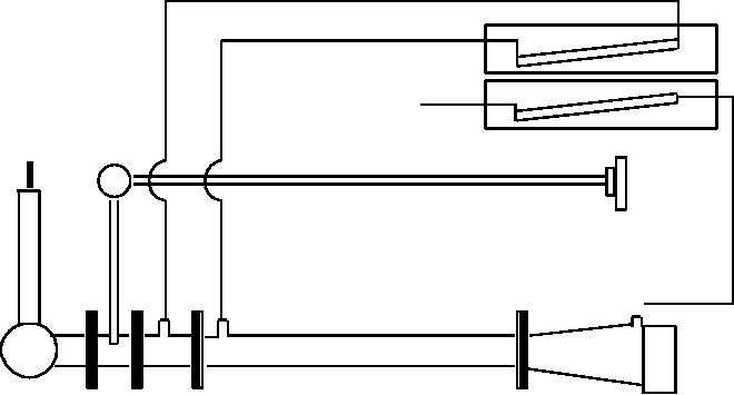
shall be made using a porosity test rig (see FIGURE 1) which has been properly calibrated.
Calibration shall be conducted on a daily basis using either a special pressure drop screen or
orifice plate in order to determine the reference setting for the orifice differential manometer, or
a correction factor that accounts for density variations of the air. Prior to sample testing, the
manometer which indicates the air flow shall be adjusted to zero with no airflow. The specimen
shall then be inserted into the sample holder until it is properly seated into the cutout. The
blower shall be started and the airflow set to coincide with the daily reference calibration setting
on the orifice differential manometer. Next, read the sample pressure drop (uncorrected) to the
nearest 0.005 inch on the 4-inch manometer (designated sample differential). The value shall
then be corrected for thickness (if other than 1.00 inch thickness) by dividing it by the measured
sample thickness. This corrected air pressure drop shall then be compared to the porosity
curve (FIGURE 2) in order to determine the average pore size for the sample specimens. The
sample pressure drop shall be reported.
MANOMETER
ORIFICE
MANOMETER
EXHAUST
ATM
SAMPLE
AIR FLOW
ADJUSTMENT
BLOWER
SLIDE
ORIFICE
SAMPLE
VALVE
HOLDER
FIGURE 1. Typical porosity (air flow) test apparatus.
16
For Parts Inquires call Parts Hangar, Inc (727) 493-0744
© Copyright 2015 Integrated Publishing, Inc.
A Service Disabled Veteran Owned Small Business